
We’re often asked, “What are some of the most common failures with ultrasound probes?”. We can confidently say, “It depends”. We’re also asked, What’s the best method of field testing ultrasound probes?”. Let’s take a look at some common problems and then some testing methods.
It’s actually model-specific
Many problems are based on the probe type. For example, 60%-70% of all TEE probes are repaired or replaced due to gross fluid invasion (or flooding) of the probe. One of the most common points of failure on standard probes (linear, curved, sector, and endo-cavity) is the acoustic array. A single, accidental, fall to the floor can shatter the fragile piezoelectric elements, resulting in image dropout. Since most of the probes in your facility are standard probes, let look at their common failures.
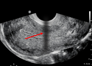
What is image dropout?
Image dropout is just that…A section of the image that has no information or that has “dropped out” (technically called hypo-echoic). Typically, this appears as a black vertical line or shadowy region of the image. Because the acoustic elements are not pulsing (or not working as expected), no information (or erroneous information) is provided to the scanner for display.
What’s the best way of field testing ultrasound probes
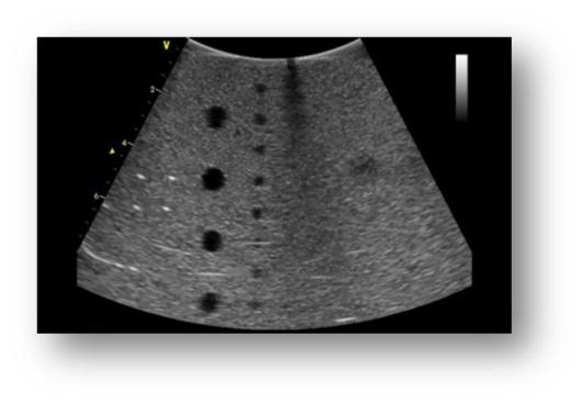
I don’t believe that anyone would argue that the best, first step is to perform a very thorough visual inspection of the probe. Performing with some level of magnification is well recommended. You can download our visual inspection guide for standard probes here. As far as image quality testing, some companies would like to sell you some very precise test equipment for assessing probe performance. Although very comprehensive, these devices just aren’t practical, nor cost-effective, for field work. They are best utilized in acoustic labs, manufacturing divisions, or repair centers, but not the field. Probe testing in the field is best performed using a tissue mimicking phantom. We published a prior post called 5-rules-for-testing-ultrasound-image-quality that discusses some key points. The post can be viewed here https://www.innovatusimaging.com/5-rules-for-testing-ultrasound-image-quality
We’ve also published a “how-to” guide for performing image quality testing. It assists HTM technicians with understanding industry standard testing criteria for assessing probe performance. The guide presents background information on transducer design, detailed testing methods, root cause analysis and troubleshooting techniques. The online version can be viewed here, but a hard copy can be requested via email at training@innovatusimaging.com
What’s another common probe problem?
Although grouped together with standard probes, cardiac probes, such as the Philips X5-1 and S5-1, and GE M5S-D experience high failure rates in the wiring harness. It not due to a design flaw or using inferior components, it’s due to the manner in which these specific probes are used in the clinical environment. I would argue that every cardiac probe will need to have its wiring harness replaced sooner versus later in its lifecycle. Innovatus Imaging engineers and fabricates over 100 different replacement cable harnesses to remedy these types of failures.
How do you know that the probe’s wiring is failing?
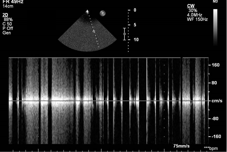
HTM imaging techs will hear reported complaints of heavy static in continuous wave Doppler mode or of color Doppler artifacts. Another complaint is of noise or other performance issues when the cable is moved or when the probe in used is a particular position.
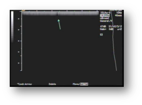
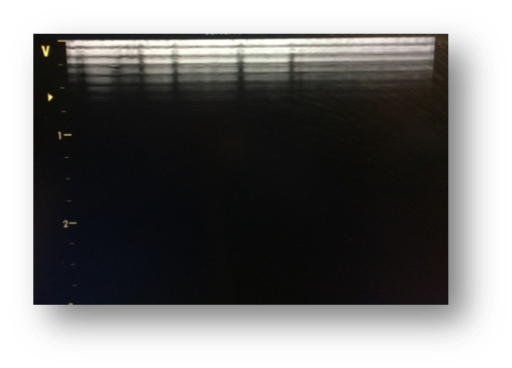
What do Doppler artifacts look like?
Well, the term artifact refers to any unwanted and unexpected anomaly in an image. Typically, color artifacts appear as unwanted flashes, vertical streaks, or areas of non-descript color variations in the image. Take a look at the photos.
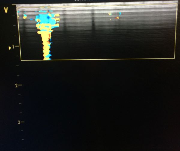
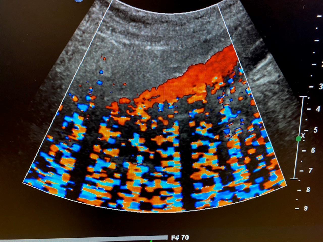
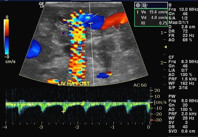
What are some causes of color artifacts?
There are many root causes, and some lie within the scanner console itself. For this discussion, let’s assume that the scanner is working as expected. One of the most common root causes is worn and intermittent wires in the probe’s wiring harness. As intermittent wires make, and break, contact with one another, the unwanted/unexpected electronic information will be displayed as flashing lines or color streaks in color Doppler mode. In pulse wave and continuous wave Doppler modes, the same information is expressed as audio static. The exact location of the flashing lines in the image is directly related to one or more intermittent micro-coaxial wires in the wiring harness. One of our most common probe repairs is replacing a worn, intermittent wiring harness.
How can the integrity of the probe’s cable be checked?
There are several methods of verifying the integrity of an ultrasound probe’s wiring harness. One that lends itself to field-based troubleshooting is below.
- With the probe connected to and initialized on the scanner, assure that the probe’s lens is clean and dry.
- On the scanner, enable color Doppler mode.
- Adjust the size and position of the color box to span the entire width of the image.
- Adjust the depth of the color box to be less than 5 cm.
- Adjust the color gain so that there is only very minor background color speckling in the color box.
- Begin by flexing each strain relief looking for flashing lines or streaks of flashing color, then flex the cable over its entire length.
- As you flex the cable, focus on any flat sections or areas that may be abraded or scuffed as the cable may have been rolled over.
If any flashes of color appear in the color box, when manipulating sections of the cable, there’s, most-likely, some intermittent wires in the harness. There’s no method to repair cable intermittencies in the field, so you’ll have to address the problem, either with a repair solution or an exchange. The cable’s integrity will only continue to decline over time.
How can we help?
Innovatus Imaging performs about 400-500 customer repairs on ultrasound probes every month, add to that at least another 200 restoring our loaner inventory. Each probe receives a thorough incoming evaluation, a very comprehensive outgoing quality assessment, and multiple in-process performance inspections. We can confidently say that our evaluation team has performed over 100,000 probe evaluations in the last 5-years. Most-likely, they’ve encountered and troubleshot almost every scenario that you and your clinicians have experienced. We welcome the opportunity to build your comfort with and competence in testing your ultrasound probes. We’re also able to assist in helping you solve any troublesome image quality problems.
When the need arises, we’d sincerely appreciate the opportunity to assist you in restoring your probe’s performance back to OEM intent. We have full repair capabilities on over 100 probe models and varying degrees of repairability on hundreds more. For more information about probe repair and our capabilities, please reach out to Ted Lucidi at TedL@innovatusimaging.com or visit www.innovatusimaging.com/ultrasound
Comments 2
Ted,
Good stuff there, man! I learned some things. I am sure we will be doing more business with you.
Best Regards,
—Mark Hayward
California Medical Devices, Inc.
925.580.1733
Author
Thanks for the kind words, Mark. Let us know if we can assist you all in any way!