
It can be frustrating to HTM teams, and end-users, to learn that their ultrasound probe, that was only sent in to address a damaged strain relief, may require a more invasive repair. Two of the most-common failures with ultrasound probes are intermittent or broken wires in the cable harness and damaged acoustic elements in the array. Damage to the acoustic array might be considered micro-damage. Many times, there are no outward indications of trauma, yet the array has sustained catastrophic damage. Let’s take a closer look at micro-damage to the acoustic array.
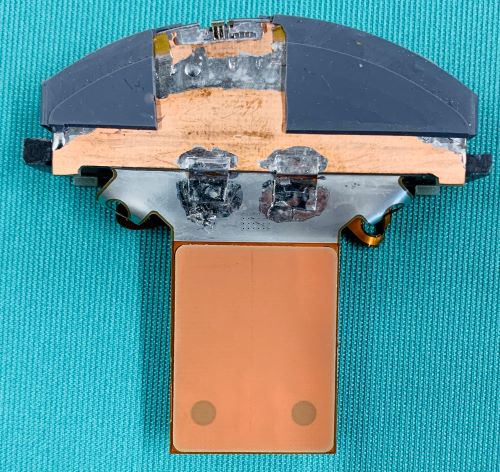
The acoustic array of an ultrasound probe might be considered a magical component to the layperson. Its piezoelectric properties enable it to convert electrical energy into sound energy AND reverse the process by converting sound energy into electrical energy. The array combines micro-electronics and precision mechanics. It’s a highly precise component manufactured to very detailed specifications and specifications are measured in microns.
Innovatus is an FDA-registered manufacturer of ultrasound probes, so we have the in-house talent, expertise, and specialized tools and instruments needed to construct acoustic arrays as well as finished-goods-quality ultrasound probes for several prominent OEMs. See some of the devices and precision equipment used in our manufacturing center by clicking here. Let’s look at the design of an acoustic array.
Acoustic Array Design
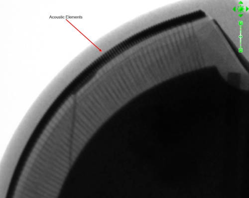
Think of the array as a sandwich that consists of multiple layers. At the core of the array are the acoustic elements which are commonly referred to as the “crystals”. Despite the size and weight of the entire array, the elements themselves, are extremely small. The height or thickness of a single element may be less than 0.4mm. Their thickness is typically compared to that of less than a hair.
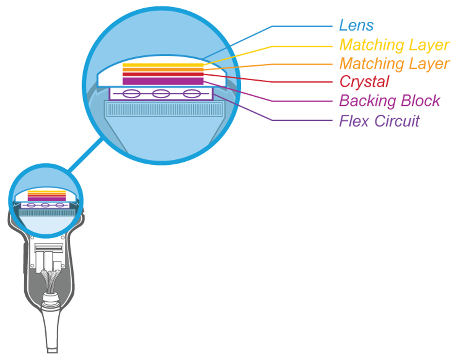


Backing Material
Beneath the array is a backing material to which the acoustic elements are bonded. The backing material serves two purposes:
- To dampen the high frequency vibrations of the elements and provide a crisp clean signal. Think of a single element as a bell. Ring a bell and the tone will continue until either A) it loses energy or B) someone grasps the bell to stop it from ringing. The backing material stops the acoustic elements from “ringing” so that they can be “rung” again…and again…and again, with high frequency ultrasound pulses, and
- To direct the energy created by the array in the appropriate direction…Out of the probe, through the lens, and into the patient. Without backing material, the acoustic energy would emanate in all directions, throughout the entire scan head, minimizing that which enters the patient.
Matching Layers
On top of the array elements are acoustic matching layers, and, ultimately, the rubber-like acoustic lens. Matching layers are designed to maximize energy transfer from the array into the patient. The scan gel, used on a probe during patient studies, serves as a matching layer. Without the use of scan gel, it’s hard to couple the acoustic energy to the body. The latest matrix array probes from Philips utilize 7-different materials on top of one another as matching layers. They’re quite complex.
Acoustic Lens
Although the acoustic lens serves as another matching layer, it’s more than just that. Being a rubber-like material, it serves as an electrical insulator against the several hundred volts applied to the array elements. It’s also a chemical barrier, sealing the internal components from potential liquid entry, such as chemical disinfectants and body fluids. The lens is also a precision component. It has a very defined thickness and shape, and is constructed of a specific material set. Lens designs typically employ a curvature to enable mechanical focusing of the sound beam to a particular distance away from the probe.
Special note regarding materials used in repair
Repairs made to ultrasound probes need to be performed using adhesives and materials consistent with the OEM design and must be ISO 10993 compliant. However simple the process of replacing a lens or strain relief may seem, repairs should not be made using standard, over-the-counter type materials such as caulking, epoxy, super glue, or standard RTV materials (which we see on a regular basis). Innovatus Imaging only uses materials which are ISO 10993 compliant and have been proven to be consistent with the OEM intended design.
Root Cause Analysis
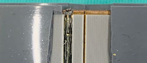
After 30+ years of repairing probes, we can say with confidence, that a strong majority of probes sent-in for repair have presented with image dropout due to traumatic array damage, yet there is no, or very little, evidence of an impact to the probe itself. How can this be? Knowing that the ceramic-like acoustic elements are extremely thin and fragile, and knowing that the scan head weighs about a pound…when a probe falls to the floor or is accidentally dropped, the impact shatters a portion of the elements. The elements no longer resonate at the designed frequency, and they fail in a certain pattern. There’s a visual signature in image quality that is easily recognized by our evaluation team. Although, acoustic and electrical testing can be used to confirm the damage, a tissue mimicking phantom and a properly configured scanner are more than sufficient.
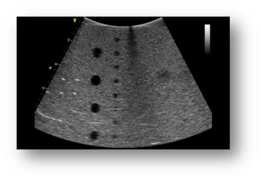
Today’s software laden scanners are capable of performing image quality “miracles”. Software enhancements, such as harmonic imaging, compound imaging, multiple focal zones, speckle reduction imaging, etc., make it possible to mask, or even hide, deficiencies in system or probe performance. Simply put, it’s possible through all of the system software, to NOT visualize image quality problems on a probe with a damaged array or intermittent wiring. Conversely, it’s actually possible to create a very poor image using a healthy probe, connected to a healthy system. Innovatus has created a how-to guide for testing image quality. It provides guidance for properly performing standard image quality tests and presents disabling software corrections. Access our How-To Guide by clicking here.
What’s All This Mean For You?
For years, a damaged acoustic array translated to a probe’s replacement. Since 2008, Innovatus Imaging has had the ability to surgically repair or fully replace the acoustic array on over 100 of the most popular probe models. By being able to repair or replace the array, fully replace the wiring harness, and performing complex electrical repairs, Innovatus is able to restore your probe’s performance…not just get it working again. And, we do so at a fraction of the cost of a replacement. For more information on how to identify array damage or to request a copy of our how-to guide, reach out to training@innovatusimaging.com
Comments 2
Wow this was great. Thank you for sharing. Brought back my days in physics class.
Thx
Chantaie
Author
Thanks for taking the time to read this post Chantaie. We really enjoy sharing details about the technology that we support.