Noise artifacts in diagnostic ultrasound images
Ted Lucidi, CBET
Today, we’re surrounded by countless pieces of technology in our everyday lives. Almost every electronic device contains some type of oscillator circuit which has the potential to affect the electro-magnetic spectrum. Call it Electro-Magnetic Interference (EMI), Radio-Frequency Interference (RFI), or environmental/atmospheric noise. I recently read an article that classified this concept as electro-magnetic pollution which is actually one of the causes of noise artifacts in diagnostic ultrasound images.
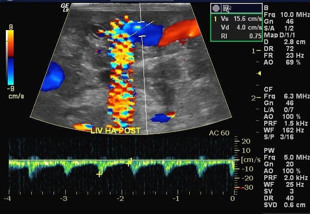
Throughout my career in ultrasound, one of the most frequent and most challenging problems to solve has been related to noise artifacts. Typically, these present as axial bands of constant or flashing color in Color Doppler mode. Intense sources of noise can affect 2D imaging in the form of faint gray, semi-axial streaks and/or semi-circular swirls overlaid on the image.
Healthcare facilities are filled with massive amounts of RF pollution. At the macro-level, X-ray generators, Electro-surgical generators, walkie-talkies, and countless wireless devices quickly come to mind. I can confidently say that there are thousands more that never would. Micro-wave ovens, florescent light ballasts, surgical lights, gel warmers, motorized doors, elevator motors, treadmills, and yes, a land-line phone are some of the more obscure sources that have, in-fact, been the root causes of noise in 2D and Color Doppler Modes. In the case of the elevator motor, troubleshooting took 3-months.
Manufacturers design their scanners and probes using various technologies to limit susceptibility to internal and external sources of RF energy. The concept of shielding is not new by any means and is credited to Michael Faraday in 1836. The main purpose is to prevent RFI from impacting sensitive electronics. In concept, it’s achieved by using a metallic screen to absorb RFI in the vicinity of the device. The shield absorbs RFI signals and funnels them to a ground connection or a virtual ground plane. By absorbing RFI signals before they reach the sensitive circuitry, the protected signals are kept clean.
Most of today’s scanners and probes are designed for increased RFI suppression. Still, there is no scanner or probe that is totally impervious to strong sources of RF energy. The amount of suppression depends on the types of technology used, the amount (or volume) of shielding and material used. Each affects the range of, the strength of, and the frequencies that can be absorbed by the shielding.
Probe Design:
As an FDA-registered manufacturer of ultrasound probes and ultrasound-related devices, Innovatus Imaging has a complete understanding of the technology and following are some common techniques for shielding used in probe design. Not all probe models are fully shielded and there are varying degrees of shielding based on the intended design provided through the engineering process.
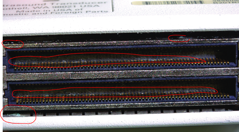
Starting at the scanhead, the array and scanhead electronics would be wrapped in a copper foil. Each wire within the wiring harness is a micro-coaxial cable, meaning that each individual wire is individually shielded, and the entire harness bundle would be housed within a wire braid. One end of the wire braid would be soldered to the foil, which surrounds the scanhead electronics and the other end would be secured to either 1) the metal connector housing or 2) a section of the connector electronics which comes in contact with a grounded area within the scanner, when connected. Ideally, the entire probe from array to connector electronics would be surrounded by a metal jacket at the same potential as the scanner ground.
Scanner Design:
Scanner technology ranges from full-size systems to hand-held devices and the need for and level of shielding, again, varies based on the intended design. Most of today’s full-size scanners are modular designs, meaning that the power supplies, front-end processor (card cage), back-end processor (typically a PC) and all accessories are separate independent devices, merely assembled into a common frame. The quality of the physical connections, of all the interconnected components, to the chassis can influence the effectiveness of the shielding. Most, or all, of the external connections to the scanner (external video, network, usb, etc.) including the probe connections are tied to some type of ground plane which ultimately are tied to the system ground.
Initial Troubleshooting:

Summary:
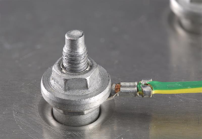
For maximum RF suppression, there should be a solid, quality connection between all shielded components, accessories, probes, and cables from end-to-end. Any compromise in the direct connection to the grounding system may cause the scanner and/or the transducers to become more susceptible to internal and/or external RFI. Next, we’ll look at some strange, but true, scenarios and a strong framework for troubleshooting noise artifacts in diagnostic ultrasound images.
Comments 1
Thank you for this information. Although I have not encountered this situation yet, I wish to be prepared. I look forward to more educational information like this.