
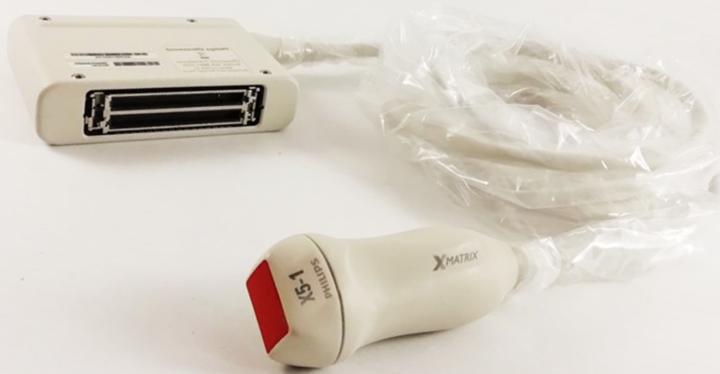
Before diving into the content below, take a few minutes to review this prior post as a primer to understand the technical complexities of the Philips X5-1.
The Philips X5-1 exhibits failures similar to other transducers…lens damage, strain relief damage, cable pulls, connector damage, premature electronic failures and, the ever-favorite, accidental trauma. For years, the primary mode of failure on almost all cardiac probes was a breakdown of the individual coax’s within the wiring harness due to the way echo studies are performed. Cable/wiring failures are still common on the X5-1, but all the technological advancements in this probe have presented new modes of failure, never seen before.
Another very common mode of failure with this probe model is constant static in CW (continuous wave) Doppler mode at only specific locations within the image. The problem may or may not actually be repeatable, which makes it extremely frustrating for echo-techs as well as service personnel. A strong percentage of the X5-1’s exhibiting this phenomenon may actually have no problem whatsoever, however; it is likely that it is THE most frequent reason for which the probe is replaced.
The engineers at our Center of Excellence have developed custom fixtures and new test methodologies to isolate and interrogate various electronics within these probes and after thorough research, we’ve identified that IF a poor, intermittent, compromised or questionable connection results on one or more of the 12 control lines within the X5-1, then constant static in CW Doppler mode may be experienced. Ultimately, ANYTHING that compromises the connection of one or more of the control lines leading to the array may result in, what seems to be, a hard probe failure. Obviously, a failure in the array/ASIC could also lead to this symptom.

Begin troubleshooting by potentially eliminating or identifying if the root cause is cable related.
- Firmly connect the X5-1 to the scanner and initialize using the Adult Echo preset. Be sure that all water or gel has been removed from the lens of the probe.
- Enter CW Doppler mode and move the sample volume cursor slightly left or right of center (Avoid a straight vertical/centered line).
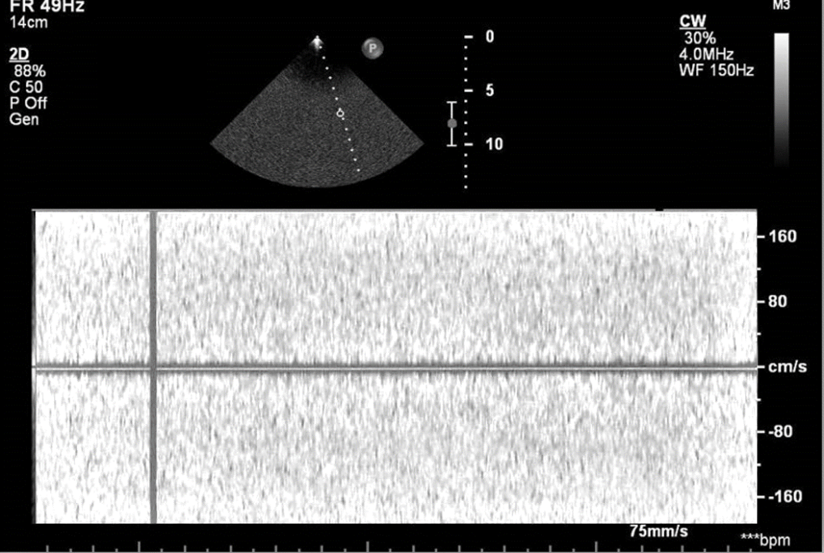
- Adjust the Doppler gain so there is very minimal or no background noise in the spectral area.
- Flex each strain relief and the length of the cable while observing the scrolling spectral Doppler area and listening to the Doppler output.
- Move the sample volume cursor to multiple locations within the image and retest.
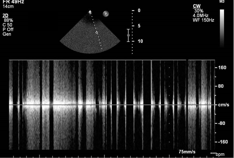
When testing factory new and slightly used probes, results will present audibly as, what sounds like, slight rubbing and visually as minor gray spikes, peaks and valleys in the spectral area. If the wires are beginning to fail (or have failed) hard/heavy static will be heard, and very pronounced white spikes will be visualized. The amount of acceptable static is highly subjective and can be interpreted differently by different people. Typically, more than one wire breaks down at a time and failures will be identified at multiple locations throughout the image. If constant static is encountered at some point, the point of failure may not be cable related.

Note: The preferred method of addressing wiring failures
is to REPLACE the wiring harness. It’s the one method that
results in restored, like-new, performance and longevity.
Ask your repair provider how they address wiring failures.
ANYTHING that compromises the quality of the connection or conductivity of one or more of the 12 control lines leading to the ASIC may result in constant static.
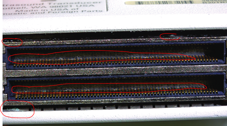
- Begin troubleshooting by thoroughly inspecting the pin bank on the reported probe and ALL ports on ALL scanners on which the probe MAY be used. Under magnification, inspect EACH pin. Look for deformations, compressed areas, oxidation and corrosion. The Compact Extreme (CX/Epiq) style connectors can be challenging to fully visualize, so use items such as headset magnifiers and dental mirrors to assist. Defects can be easily missed. It’s also possible that a single bent pin on a single probe has compromised the connectors across multiple ports on multiple scanners. The damage to one port, then affects the next probe connected. So on and so forth.
- Consider that the spring tension of the pins on either the single X5-1 or the scanner(s) has weakened or deteriorated to a point where it affects the Philips X5-1.
- Don’t assume that because other probe models don’t experience this scenario that the problem is not scanner related. So far, we’ve identified that this failure is isolated to the Philips X5-1 ONLY.
- Also, don’t assume that replacing the probe will solve the issue. It may, but may only for the short-term. The spring tension of the pins on new probes may be better than on used/older probes but using a new probe on a scanner that has worn/compromised connectors can result in the same problem arising later.

When complaints of constant static arise, actively work with your sonographers. When the issue is encountered, or when troubleshooting, work together.
- Have the sonographer disconnect and reconnect the probe. This may solve a temporary seating/connectivity issue
- If the problem persists, disconnect the probe and reconnect it to a DIFFERENT port. Spring tension can wear, and oxidation can build up on probes/scanner ports over time, even if the probe is never disconnected.
- Finally, test the affected probe on another scanner. As with most performance testing within ultrasound, consistency is key. Test the probe using the IDENTICAL settings with the Doppler sample volume in the IDENTICAL location. To help, capture photos of the scanner settings and sample volume locations using a mobile device.
On the surface, replacing a probe may seem like the easiest solution to troubleshoot or solve this particular failure. With today’s more advanced probe designs, you may just need better tools in your toolbox. Make sure to partner with a provider that has advanced as much as the products you support.
Access this material in a downloadable version below