
Despite advancements in matrix array technology, mechanical 3D probes still remain very popular for abdominal and Ob-Gyn applications. Given their design, there are modes of failure specific to mechanical 3D probes. Throughout our history, Innovatus has repaired over 12,000 mechanical 3D probes. We wanted to share with you a little about the technology, the modes of failure, and some tips for troubleshooting mechanical 3D ultrasound probes when you’re in the field.
Mechanical 3D Probe Technology
Mechanically acquiring a 3D image requires that the acoustic array be oscillated back and forth, while multiple single images (or slices) are acquired by the scanner. The multiple images are then integrated with one another and assembled to render the 3D image. A lot of technology is required to make this happen. The probe as well as the scanner require additional electro-mechanics.
Within the probe, the array is mounted to a plastic assembly that allows it to pivot on metal hinge points (details important later). A motor and push/pull mechanism oscillate the array, while sensors determine the motor’s speed and position. The entire upper half of the probe’s electro-mechanics are encased within an oil-filled bladder to allow for lubrication and acoustic coupling. On top of the probe is a soft rubber dome, which acts as the top of the oil bladder, and is the area that contacts the patient. The scanner also requires additional complexity. There’s usually a dedicated motor control PCB and additional power requirements to manage the probe’s electro-mechanics.
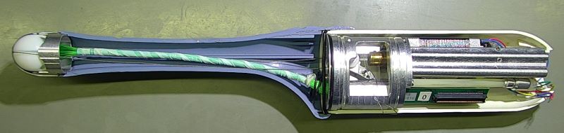
- The white section contains electro-mechanics to oscillate the array
- The entire blue section is filled with a highly specialized medical-grade oil
- The white “egg” houses the acoustic array
Mechanical 3D probes, just like all other ultrasound probes, are subject to normal wear due to continued exposure to harsh chemical disinfectants and repeated cable flexing. Even when using approved chemicals properly, seams and seals will deteriorate over time. Using approved chemicals improperly, or unapproved chemicals, has the potential to significantly accelerate wear and tear. While image dropout and mechanical damage are common to all probe types, they may actually be more prevalent with mechanical 3D probes.
The added technology within a mechanical 3D probe not only increases its size but can almost double its weight when compared to its 2D counterpart (GE RIC5-9-D versus GE IC5-9-D). It also introduces additional points of failure.
Air Bubbles
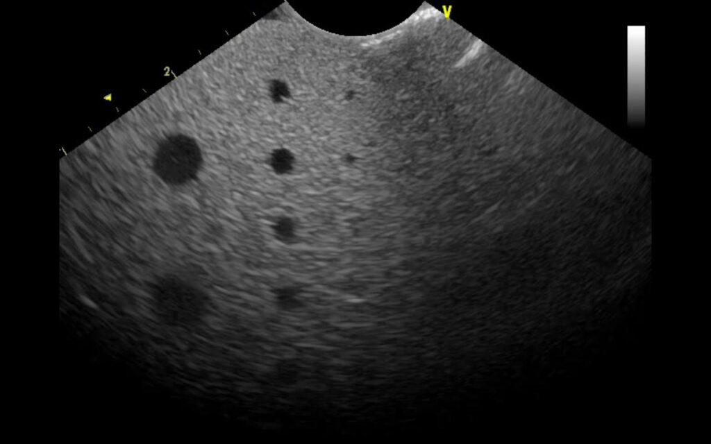
Like all mechanical components, those inside 3D probes are subject to wear. Combining this with any small amount of accidental trauma can introduce a variety of new problems. A common problem is deterioration of or damage to the internal seals on the oil bladder, which results in an internal leak. This usually begins to present itself as air bubbles casting shadows in the image (that move based on the probe’s position or orientation) but can progress, depending upon severity, to oil draining from the probe housing. The same problem can occur externally to the dome. We’ve seen everything from small punctures and slices to the entire dome itself missing. Although its possible for chemicals to damage the seal between the dome and probe housing, most failures are a result of trauma or improper / unqualified adhesives used to install or repair.
The non-uniformity (shadowing) on the right side of the image may be due to an air bubble, within the dome, that has migrated between the array and the inside of the dome.
Rebuilding of the fluid system is a complex process and requires the use of proprietary instruments to ensure the proper / qualified fluid is degassed; if not, micro-bubbles will soon aggregate and create image artifacts. Most repair providers are not equipped to PROPERLY perform this task.
Error Codes
When a mechanical 3D probe is plugged into a scanner and selected by the user, the probe undergoes an initialization process. The scanner attempts to initialize the probe’s electro-mechanics, determine the motor’s position, and exercise its range of motion. If any of these items aren’t within the acceptable range, the scanner displays an error message. Common error codes are below:
- Philips: Error 30
- GE probes (RICs, RABs, etc.): MotCntl: No Reference Position Signal
- Both error messages instruct users to disconnect/reconnect the probe to reinitialize the electro-mechanics
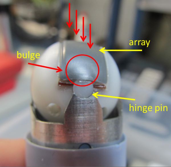
There are instances when sensors and electronics fail, but the root cause of most of these errors are due to user induced problems. The most frequent cause is trauma to the top of the probe. As mentioned above and shown here, the array is mounted to a plastic assembly that oscillates on metal pivot points. An impact to the top of the probe can sheer-off the plastic hinge pins or jam the mechanics. You may experience decreased range of motion, no oscillation whatsoever, or intermittent operation depending upon severity. In some instances, you may immediately encounter an error. Other times the probe vibrates or works intermittently. Other causes for these errors are gross fluid invasion short circuiting the probe’s electro-mechanics or intermittent wiring in the cable harness.
What to do if you have a problem
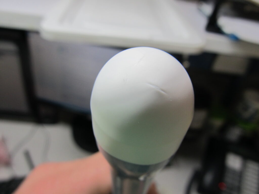
The first step in any troubleshooting tree should be a thorough visual inspection. Starting at the top of the probe, look for the appearance of scuffs, dents, or impact marks to the dome or probe housing. These would be strong indicators of internal mechanical damage. The dome should appear uniform in shape. Any bulges or malformations are indications of internal damage, such as the array becoming unseated from its pivot points. On the probe housing sections, examine all joints where the various sections meet. There should be no oily sheen or residue, and by no means any fluid, oil or otherwise, leaking from the housing.
Troubleshooting Mechanical 3D Ultrasound Probes
In the field, a solid process for troubleshooting mechanical 3D ultrasound probes is to:
- Initialize the probe on the scanner
- Place the scanner in continuous 3D acquisition mode
- Apply very gentle pressure to the top of the dome using the palm of your hand.
- With gentle pressure applied to the dome, no error message should present.
If a mechanical failure exists, or if excessive pressure is applied to the dome, it may hinder the probe’s operation and induce an error. You should also wiggle the cable through its entire length inspecting for any intermittencies.
How We Can Help
Innovatus Imaging supports the most popular 3D imaging probe models, whether mechanical or matrix technology. Multiple models are fully repairable, meaning that you’re not presented with costly options for replacement…Just cost-effective repair solutions.
Our approach to repair with mechanical 3D probes is such that we fully rebuild the fluidics system anytime there is invasive work performed. It’s a key factor to our 6-month warranty period resulting in an extremely negligible return rate.
Comments 2
Hello.
This is Phillip and a biomedical engineer from Uganda
My client called for his us probe.
One part of the screen is dark and another part is light
Author
Hi Phillipo,
If the probe is a mechanical 3D probe, there could be an air bubble in the fluid system. Typically, large shadows can be result of a air bubble between the array and the dome. One way to verify this is to hold the probe vertically and observe the image. Tilt the probe slightly and see if the shadow migrates. Air bubbles can be common in mechanical 3D probes, especially probes with years of use. The seals inside of the probe may have aged and allowed air to displace the oil. There may also be signs that the oil that has leaked from the probe.